{The document was scanned from the original using Optical Character Recognition in January 1998. Some errors or variations from the original may exist. Comments added to clarify points that may not be obvious or to indicate changes to the original document are inclosed in curly braces "{ }" such as this introduction. Some corrections (e.g. spelling) and format editing were made without indication. Due to the poor quality of the original, equations were recreated rather than scanned. Comments, editing, equation creation, and scanning by R.L. Cross, from January 1998 to ??? 1998 }
GROUND EFFECTS:
{In the original J.H.Richmond computer program there was no provision for a groundplane.} In the modified antenna analysis computer program, finite and infinite {conductivity} ground effects were added by using the reflection coefficient technique. The method in which this technique was used required the generation of an image structure. In this section the reflection technique will be discussed in detail. In order to apply ground effects to the electric field, the field for the image structure was first calculated as if a ground were not present, Then, the field was decomposed into parallel and perpendicular components. (A parallel component is the component which is parallel to the plane of incidence. A perpendicular component is one which is perpendicular to this plane. The plane of incidence is the plane containing the normal to the reflecting surface and the incident ray.)

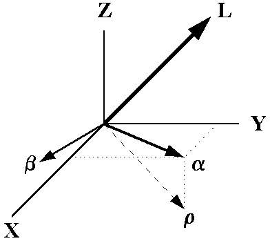
Consider an image monopole with the electric field in the L direction. The ray,
![]() is a vector which is perpendicular to L and passes through the point of interest.
To apply reflection technique, the plane of incident must be found. It is advantageous to
define a new coordinate system (
is a vector which is perpendicular to L and passes through the point of interest.
To apply reflection technique, the plane of incident must be found. It is advantageous to
define a new coordinate system (![]() ,
,
![]() , z)
where
, z)
where ![]() and
and
![]() {are} parallel
to the xy plane with
{are} parallel
to the xy plane with ![]() in the
plane of incident and
in the
plane of incident and ![]() perpendicular.
If the direction cosines (cosx, cosy, and cosy) are known, it can be shown that the components of the
field in the
perpendicular.
If the direction cosines (cosx, cosy, and cosy) are known, it can be shown that the components of the
field in the ![]()
![]() plane {i.e. the xy plane} have the
following relationship:
plane {i.e. the xy plane} have the
following relationship:
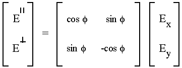
where ![]() = arctan(cosy/cosx).
Now the reflection coefficients for the interface can be applied as:
= arctan(cosy/cosx).
Now the reflection coefficients for the interface can be applied as:

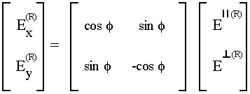
(the square matrix is unique, in that, the inverse is equal to the original matrix). Since the image direction is opposite to the original monopole, that is,
the z component of the field, which is in the plane of incidence, is given by:
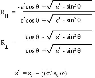
From electro-magnetic theory the reflection coefficients for the fields in medium (1) at the interface with another medium (2) are defined as:
 for the perpendicular component
 for the parallel component
where ![]() is the angle of incidence as measured from the normal to the interface and
is the angle of incidence as measured from the normal to the interface and
where the subscripts correspond to the mediums above.
To determine the relationship between ![]() ,
,
![]() and
and ![]() ,
,
![]() a perfect ground (infinite conductivity with relative dielectric constant of zero) was investigated.
a perfect ground (infinite conductivity with relative dielectric constant of zero) was investigated.
But, for a perfect ground the contributions to the field from the image monopole would be equal to the field of the original monopole but opposite in sign due to the chosen reference direction,

therefore

In summary, the contribution to the electric field of a monopole over a ground plane at a given point is given by:
where
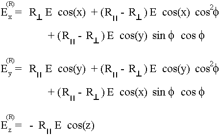
where E is the field without the ground plane present and
Return to System Manual
Goto User's Manual
See also the quick reference for the user's guide.
Goto Examples page
Goto Download Page
Return to ASAP Homepage
Last modified on: 3 Nov 2007