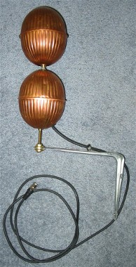
A Picture of the overall antenna mounted on an angle bracket.
The main points of this was
I succeeded on all three points! ** Well except for 'off-the-shelf'. I had to cut some holes and there is one step that is tricky involving drilling a hole lengthwise down a brass screw... but other than that.
Below I give some rough ideas how to make one of your own but I don't give step-by-step construction details.
Note that this thing as currently built isn't rugged enough for permanent outdoor mounting.
A Picture of the overall antenna mounted on an angle bracket. |
|
These VSWR measurements were made with a HP 8753E Network Analyzer. I took the antenna into work and grabbed the data off the analyzer then plotted it using MS Excel® . I hypothesize that the main reason the VSWR is not so pretty above 2 GHZ is that the cable and BNC connectors are not really good enough. It would be interesting to see what would happen if good quality microwave connectors were used.
Wait a minute ! What about Gain !
Sorry, I didn't have the facilities available to make gain measurements. Based on basic antenna principles it has to be at least as good as a dipole antenna. If it weren't for the loss from using off-the-shelf BNC hardware it might even be better at the higher frequencies due to it simulating a flared horn rotated about the vertical axis.
Maybe I can convince someone at work or somewhere into doing gain measurements for me later.
Even though I don't have gain measurements, I know it does work in real life on a real radio system. Right after I built it, for fun I took it out on a business trip to a military flight-test range where our company was testing one of our new data-link radios with military jets and other aircraft. After the official testing for the day was done at our main ground site, we took the rather sizable and (supposedly) optimized omni-directional antenna we use for testing down off of the mast and replaced it with this thing. One of our other ground network stations on a mountain some miles away was still operating and we compared notes. It worked great! It came out only a few points lower on the linear correlation score. It also survived the ~ 100 watts of power at L-band that the transmitter put into it.
Construction
I am not going to give detailed instructions but here are the basics.
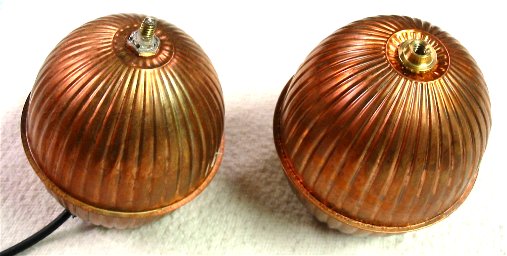
|
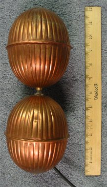
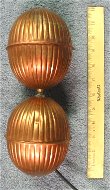
On the left you see a photo of the assembled antenna without the mounting bracket. The ruler gives a size reference. In what follows I will refer to the two copper floats that make up the antenna as the "top float" and the "bottom float" which correspond to the top and bottom floats as shown in this photo. Only the bottom float has to be modified; the top float is used as-is right from the hardware store bin. The bottom float is only 'modified' by drilling some holes. The hardware is then attached. The idea was to do as little work as possible and use as much off-the-shelf stuff as possible so I just used prefabbed BNC connectorized cables and didn't roll my own. One end of the BNC cable gets connected to whatever electronic or radio project you want to use with the antenna; the other end gets connected to the BNC panel mount connector that is mounted to the bottom float. This technique eliminates a lot of guesswork about how to best make a feedpoint that keeps the impedance match correct. The use of the off-the-shelf BNC cable and BNC panel mount is probably the main reason the antenna doesn't work better above 2 GHz.
|
OK, slightly more detailed steps (more detailed pictures below):
Here is a photo of the bottom and top separated. The one on the left is the "bottom" piece and is the only one that is modified. The top piece (on the right) is used "as is" from the hardware store.
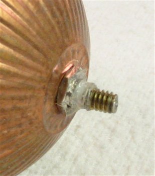
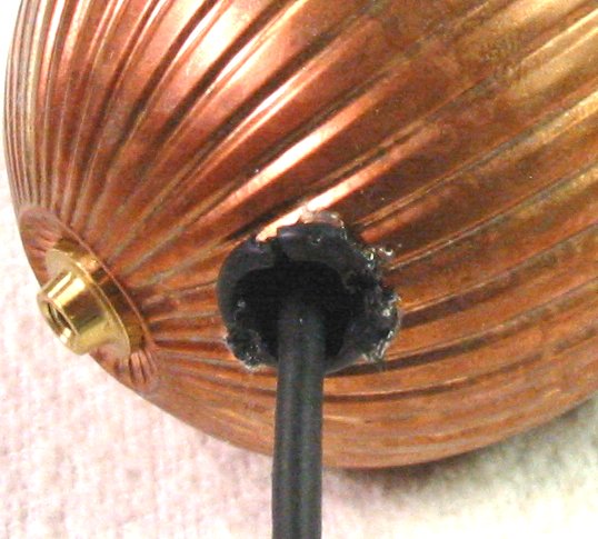
A close-up photo of what the brass thread soldered to the BNC panel mount looks like with the panel-mount properly installed into the float and with a small bead of 'hot-glue' strengthing the junction between the thread and the panel mount.
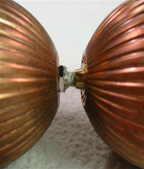
Close-up of what the feed point should look like with the whole thing put together.
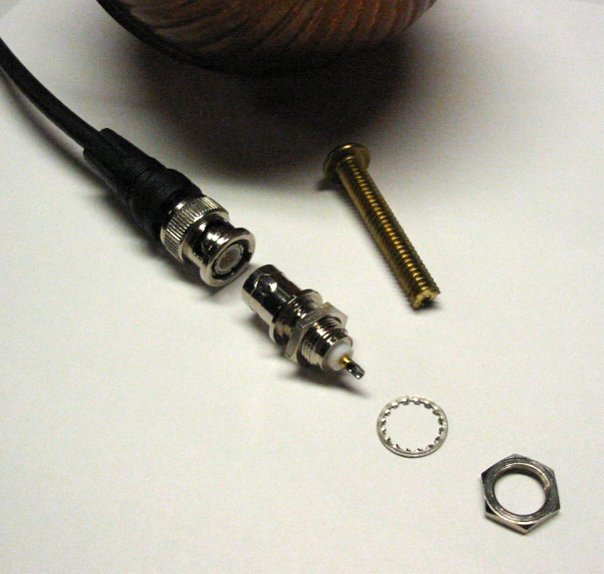
The BNC coax cable, the panel mount connector and the washer and nut that is used outside the float to hold it in place. The brass screw shown is actually the remnant of the one used to create the short piece with the hole in it. (I neglected to take a photo of that piece before it got soldered to the {other} BNC panel mount -- sorry). The BNC coax cable is connected to the panel mount and then the panel mount (along with the one nut that is show on it) is put inside the float.
The "bigger" hole near the bottom of the bottom float through which the whole BNC panel mount connector attached to the BNC cable is passed. A grommet was cut and 'hot-glued' into place to avoid having the sharp edges of the hole chafe the cable insulation.
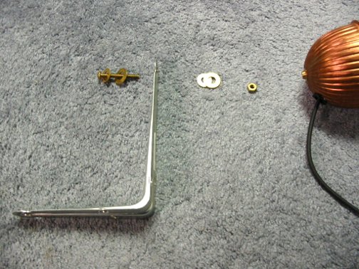
The bracket hardware to attach to the bottom float (fairly obvious).
So why did I think this idea might work before I started?
Well, antennas have been a sort of interest of mine ever since I was in high school and became a ham radio operator. I have read a lot of articles on antennas over the years and knew that biconical antennas were wideband and also that tapered horn antennas were wideband. More recently there have been papers collecting wideband antenna information for the purpose of UWB (ultra-wide-band) radio systems that show the use of tapered and elliptical planar elements. Since every trip to the hardware store (for whatever purpose) is also for me an exercise in thinking about what weird use I could put all the various hardware and plumbing supplies for radio and antenna purposes, it was only natural that one day the idea of trying copper toilet floats for something would come around. When it did I held one above the other and realized that they looked just about right (from memories of figures in antenna books) to be approximately correct angles for a 50 ohm biconical antenna or the right shape to form a type of tapered horn / slot of revolution about the vertical axis. Both of this properties speak immediately of broadband potential. Also, I thought it might be possible that a slight gain over a dipole might be possible at higher frequencies where the wavelength is small enough so that the gap between the two floats simulates a tapered horn in cross-section.
I must admit that I am not the first person to think of using copper floats for electronic purposes. Once, in a former job, I traveled to a lightning testing laboratory to have some aircraft skin samples tested. Now this was many years ago so things may have changed but, I was highly impressed that they had constructed most of the test apparatus from locally available hardware-store and electric utility parts. This included the 1,000,000 Volt + voltage multiplier tower that used... yep! copper toilet floats at the elements of the spark gap switches. These switches are used to switch the tower from charge to strike through a physical movement of one set of float towards another. There was no need for those highly polished silver colored spheres that you see in the high energy physics labs. So that planted a seed for their use also I suspect.
Comments? Then email me (but you have to type in the email address yourself):
Ray L. Cross, ![]() , WK0O,
, WK0O,
BSEE, MSEE,
and sometimes Webpage Curator
Last modified on: 3 November 2007